Varsha is a student of SkoolOfCode. Varsha loves to keep herself up-to-date with new technology and product updates She is learning Microbit and loves to use her Microbit to interact with a real-time environment. She loves to use Microbit in real-time projects or to provide solutions to existing problems. She is building a Microbit bike tail light since last month. She wants to build this Microbit based bike tail light with light sensor so that it can be used by bikers at night time for their safety.
She has chosen Microbit courses because she believes in the fact that this little technology cannot just help us learn to code better but also have smart abilities to interact with the outer world. Though being small in size, Microbit is powerful enough to provide sufficient data from our surroundings through their onboard sensors. The light sensor on Microbit is perfect for this project as it can detect the light level and accordingly change the pattern of LEDs.
What is a light sensor?
A light sensor is a device that detects the presence and intensity of light. Light sensors are used in a variety of applications, including photography, videography, automatic street lighting, security cameras, and many others. For example, you can program your Microbit to perform a specific action depending on the ambient light conditions. For example in this project all the LEDs on the Microbit turn on when it is dark outside. The light sensor is used to detect the darkness or brightness and then that information is used by the microbit to create different LED patterns.

Let’s explore where is the light sensor on Microbit
The LEDs (light-emitting diodes) on the Microbit come in a 5X5 arrangement. The LEDs act as input and output devices also. There are 25 LEDs on the Microbit grid. Out of the 25 LEDs, there are 6 LEDs that act as a light sensors. This means the Microbit doesn’t have an onboard light sensor. It uses LEDs to provide an approximation of ambient light. So, the LEDs sense light levels and hence work as an input. On the contrary, the LEDs give out light so that we can see it and hence work as an output. The range of the light sensors is 0 to 255 which means 0 for dark and 255 for extremely bright. Refer light sensor documentation for more detail.
The logic of the Code
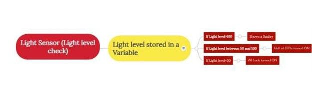
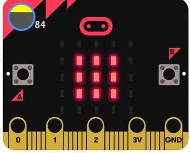
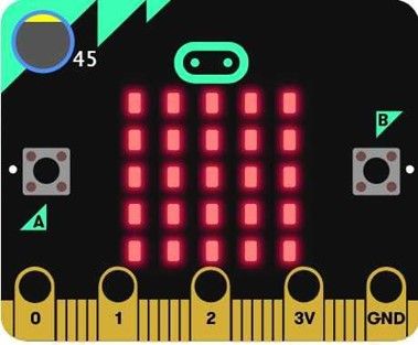
The light sensor continuously checks the light level. The value of the light level is stored in a variable. Depending upon the value of the variable the Microbit LEDs can turn on or off in different combinations. If the value of the light level is less than 50 (that implies it is dark) then all LEDs will turn ON. If the value of the light level is between 50 and 100 (that implies it is neither dark nor sunny) then half of the LEDs will turn ON. If the value of the light level is greater than 100 (that implies it is sunny) then a smiley will be displayed.
Now let’s write some code for this project:
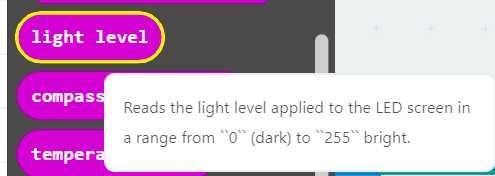
For Coding Microbit we are using Makecode which provides block coding for kids and can be accessed at www.makecode.microbit.org. The LEDs on the Microbit grid work as input recording light level values. So on the Makecode editor, we will proceed to the Input category and we will use the block light level as shown below.
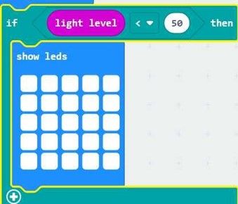
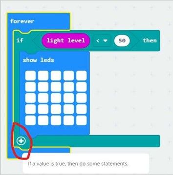
The light level is in the range of 0 to 255, i.e. a number. So, we will check whether the value of light level is less than 50 though a conditional as shown below. The show LED block is used to create a pattern (all LEDs on).
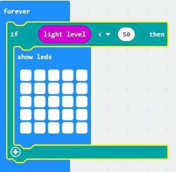
We want that the condition to be checked forever so we will put this conditional in a forever loop.
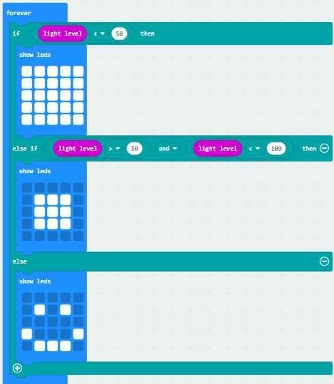
After this, we want that the Microbit should also check the light level for two more conditions: whether the light level is between 50 and 100 and whether the light level is greater than 100 (i.e. the only condition which is left so we can use the else part). Therefore we will extend the if loop by clicking on the + sign as shown in the picture.
After extending the if loop we will put the required conditional statements for the light level. The final code for your reference is shown below.
Time to test the Code
The Code can be tested in the Makecode Simulator. So let’s test the code. We can vary the light level by moving the yellow part on the Microbit Simulator. We can change the reading of the light sensor and observe the different LED patterns.
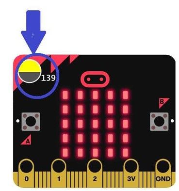
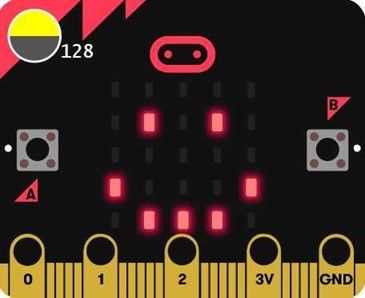
The different LED patterns observed for different light levels are shown below (for all three cases).
Let’s download the Code on Microbit to have some real-time fun
Connect the Microbit to the USB port of your laptop/desktop. Click the download button on the Makecode Editor. The hex file will be saved in the Downloads section of your computer. Copy the hex file and paste it onto the Microbit drive. Now we can remove the microbit cable and connect the microbit with the battery. For more information regarding the download process Book a FREE trial class today.

The Microbit rear light is ready. Connect the Microbit on your bike and let’s go for a ride. This project is a great way to use your Microbit for a real-time problem. You can also extend this project by adding a digital magnetic compass that will guide you in your biking trips. At SkoolOfCode, we offer coding classes for kids where students get a chance to work on such amazing projects under the guidance of our trained tutors. Happy Coding and have fun flashing your Microbit bike rear light!!!
